Types of losses in utility-scale PV systems
There are several different types of solar system losses with various causes, such as the environment, weather, and load. Most are issues that need to be addressed at the design stage, while maintenance can go some way to limit those losses.
Shading losses
Shading the surface of solar panels from direct sunlight can result in around 7% system loss. As solar cells are linked in groups, the shading of one cell blocks part of the power flow and affects the entire panel’s output. Disruptions to the flow can also cause hot spots, which can damage the panel.
The extent of shading loss is primarily influenced by the plant design — key elements such as the pitch distance, and the location of the panels to avoid buildings, trees, and other light obstructions play a significant role. But regular maintenance can also reduce shading losses by ensuring that panels do not become overshadowed by new trees and plants, or other structures.
Modern PV panels have bypass diodes, which enables the current to flow around cells that may be blocked by shading. However, the cell output is still lost and bypass diodes are prone to failure.
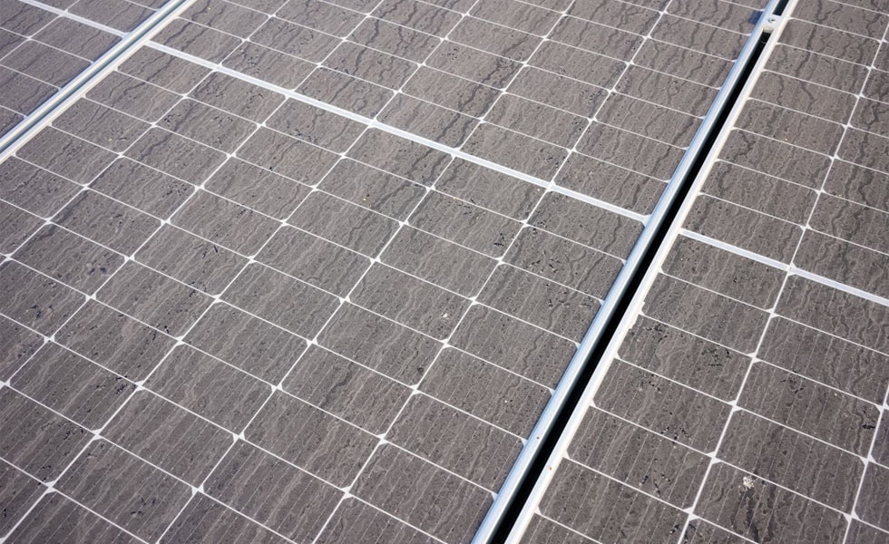
Dust and dirt
Soiling from dust and dirt can average around 2% system losses in locations where there is rainfall throughout the year. But at sites near industrial centers and in dusty regions with limited rainfall, losses could reach 6-7%.
The angle at which panels are tilted affects the buildup of dust or snowfall, while other obstructions such as bird droppings can accumulate over time and become difficult to remove.
The tilt angle is determined during the design stage and can be adjusted to reduce dust and dirt accumulation while taking into account other factors, such as the optimal angle for sunlight absorption and shading from adjacent rows.
Maintenance is important for reducing soiling losses, as cleaning panels every six months can increase output by 3-5% on average, and as much as 25% in dusty locations. While rainfall can remove some dust and dirt from panels, it is unlikely to clean off all surface grime and is not a substitute for regular cleaning.
Reflection
There is some loss of output around 2.5% when sunlight reflects off panel surfaces rather than being absorbed to generate a current. Solar panel designers continue to research ways to increase efficiency by reducing surface reflectivity to boost light absorption.
At the project stage, the choice of panel is an important consideration to reduce reflection losses. Using granular paint additives to roughen panel surfaces or adding another light-trapping mechanism can also limit losses.
Spectral
Solar cells do not convert all of the light wavelengths the sun transmits. But they are optimized to broadly convert most of the visible light and half the infrared light that hits them, maximizing electrical output. Manufacturers are working on ways to increase light absorption from different wavelengths, but this is difficult to address at the project design stage.
Light-induced degradation (LID) affects a large volume of crystalline silicon cells in the first few days after they are installed due to exposure to sunlight. This can cause losses of 0.5-1.5% but only affects certain module types, making the choice of module an important factor in limiting losses.
Irradiation
The reduction in irradiation is referring to the Standard Test Conditions (STC) rating results. In real life, the modules will not be operating at the STC conditions, therefore there’s a degradation in efficiency close to 1.5%.
Thermal
One of the biggest system losses is caused by high temperatures — for every 1°C above 25°C the output from a solar cell drops by 0.5%. Researchers continue to look at ways to reduce thermal losses, such as increasing air circulation.
Proposed hybrid PV-thermal solar panels are designed to cool the cell surface with water and recover the heat they generate for use in buildings or other applications.
Array mismatch
Mismatch occurs when two or more panels produce different levels of energy, either because of partial shading, different string lenghts, or slight differences in the electrical characteristics of the cells. There can be mismatches in entire strings because of poor orientation or panels facing in different directions.
Besides this, the manufacturing process naturally results in slight variations as no two modules are entirely identical. Cells are manufactured with a tolerance of between +/-1.5% and +/-5%, so in real-world conditions they will not produce identical amounts of energy. Modeling tools such as RatedPower’s pvDesign, allows users to choose the value for this module quality, as well as the mismatch caused by the varying power of these modules which will originate some electrical loss.
DC cable losses
Losses from current flowing through DC cables cannot be eliminated but they can be minimized. Electrical resistance causes voltage to drop in the cables when the current flows, and power is lost through heating. The higher the current the greater the heating effect and the more it becomes a factor across connections.
Correct design and regular maintenance of the cables are the main ways to reduce energy losses from DC cables. PV system designers use cable sizes that limit losses to less than 1% of peak output.
Inverter losses
For utility scale solar projects we have string and central inverters. They usually have an efficiency rate of around 95- 98%, but it can change depending on other aspects. Two of the most important factors that affect inverter efficiency are temperature and load. It is important to ensure that inverters are well-ventilated and shielded from direct sunlight, and plant designers should also make sure inverters are correctly matched to the panels and are not too small or too large — particularly if the system will be expanded in the future. On average, the inverters should be replaced every 10 years.
AC cable losses
As with DC losses, system losses from AC cables are unavoidable and project designers typically account for losses of 1%. The only way to limit AC cable losses is by selecting the correct components and installing cable runs of appropriate sizing with the shortest lengths possible.
Plant engineers assume another 2-3% in losses from equipment downtime as a result of faults or grid outages. Panel degradation causes around 0.8% in power losses every year.
Tags :